We use cookies to provide you with the best possible experience. They also allow us to analyze user behavior in order to constantly improve the website for you.
The consent is voluntary. You can withdraw it at any time or renew it in Cookie settings on the home page. Withdrawal of your consent does not affect the lawfulness of processing performed before the withdrawal.
Privacy Protection Policy
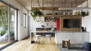
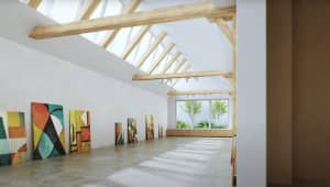
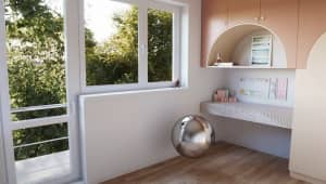
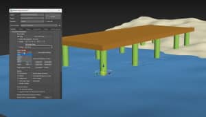
In this walkthrough, we guide you through the process of building a polished 3D interior scene inspired by the cover of Archmodels vol. 306 – Table Sets.
In this walkthrough, we guide you through the process of building a polished 3D interior scene inspired by the cover of Archmodels vol. 306 – Table Sets.


 Customer zone
 Your orders
 Edit account
 Add project
 Liked projects
 View your artist profile